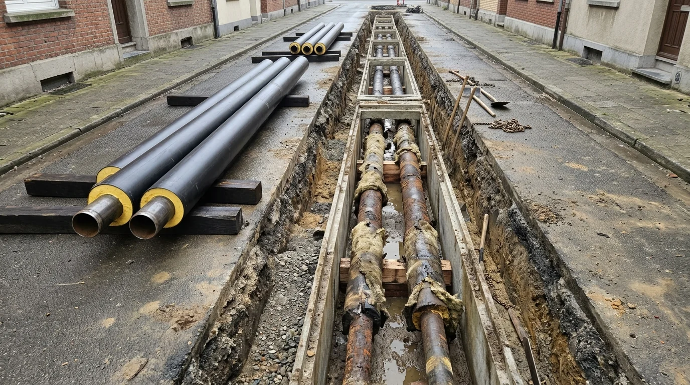
Evaluating district heating pipes during municipal trench excavations requires separating short-term leak patching inside legacy concrete channels from full-segment replacement with directly buried pre-insulated bonded pipe assemblies. Second-generation European district heating networks developed between the 1930s and 1970s routed pressurised hot-water pipes inside concrete ducts, whereas third-generation networks introduced in the 1970s use pre-insulated pipes directly buried underground. In June 2024, the Euroheat & Power survey (2022 data) identified 19,037 district heating networks across surveyed European countries supplying heat to over 77.3 million people, with a 42.6% share supplied from renewable and waste heat sources.
In Ukraine, donor-backed utility rehabilitation connects pipeline-level engineering directly to wider Ukraine infrastructure recovery and macro-level municipal water and heating grid recovery. Created in spring 2022 in coordination with the European Commission, the Ukraine Energy Support Fund (UESF) finances spare parts, technical resources, fuel, and services needed for heat supply, with its cumulative budget exceeding 2 billion from 39 donors in 26 partner countries. When utility crews open a damaged thermal main, EN 253:2019 specifies requirements for straight lengths of factory-made thermally insulated bonded single pipe assemblies for hot water networks in accordance with EN 13941-1, comprising a steel service pipe, polyurethane foam thermal insulation, and a polyethylene casing.
| Engineering parameter | Legacy concrete-duct mineral wool system | Directly buried pre-insulated bonded pipe system |
|---|---|---|
| Network generation and burial architecture | Second-generation European district heating networks developed between the 1930s and 1970s routed pressurised hot-water pipes inside concrete ducts | Third-generation networks introduced in the 1970s use pre-insulated pipes directly buried underground |
| Governing system design and temperature rating | n/a | EN13941-1 (2019) specifies design, calculation, and installation requirements for directly buried bonded hot water piping systems operating continuously with treated hot water at temperatures up to 120 deg. C, with occasional peak temperatures up to 140 deg. C and a maximum internal pressure of 2.5 MPa. According to the EN253 standard published in 2019, the minimum lifetime of a district heating pipe used continuously at temperatures up to 120°C must be 30 years, while at operating temperatures below 115°C the pipes may last for more than 50 years |
| Insulation moisture response and thermal conductivity | Prior mineral-wool studies found that the effective thermal conductivity of wet mineral wool is 50-fold larger than the dry sample, and Aspen Aerogel tests reveal that submerged wet insulation experiences over 30-fold greater heat loss compared to dry insulation | According to EN253, the maximum initial thermal conductivity of rigid PUR foam should not exceed 0.029 W/(m K) at 50°C. Cyclopentane blowing gas has a thermal conductivity of 0.013 W/mK at 25°C; PUR foams consist of 92–98% closed cells |
| External steel corrosion exposure | In 720-hour modified ASTM G189 cyclic wet/dry testing (60°C / 140°F wet and 150°C / 302°F dry), steel pipe insulated with uninhibited mineral wool suffered an average uniform corrosion rate of 358.18 µm/year (14.10 MPY), compared to 8.53 µm/year (0.34 MPY) for mineral wool with corrosion inhibitors | Prior to thermal insulation, the outer surface of the steel service pipe shall be cleaned free of rust, mill scale, oil, grease, dust, paint, and moisture, and before cleaning it shall comply with rust grade A, B, or C according to EN ISO 8501-1, without pitting |
| Moisture surveillance and fault location | n/a | EN 14419:2019 Clause 1 specifies requirements and test methods for electrical-wire-based surveillance systems forming an integral part of pipes, valves, fittings, and joints in directly buried hot water networks in accordance with EN 13941-1 and EN 13941-2 |
Ukrainian Concrete-Channel Pipe Inventories and Wet Mineral Wool Failure Physics
World Bank municipal network audits document the overwhelming share of concrete-channel district heating pipes relative to pre-insulated polyurethane networks prior to rehabilitation:
- In Kamianets-Podilskyi (KP-MTE), the 62.5 km district heating network (diameters 50-600 mm, linear heat load density 1.56 Gcal/h per km) had a 7.3% pre-insulated pipe penetration rate, while 93% of pipelines were ‘Soviet Type’ pipes installed mostly underground in concrete channels insulated with asbestos-based mortar, glass wool, or mineral wool and bitumen board coating.
- In Kharkiv (Kharkivski Teplovi Merezhi), the 1,594 km two-pipe-equivalent network (diameters 40-1220 mm, average age 50 years) had a 7.0% pre-insulated pipe penetration rate, while 93% were ‘Soviet Type’ insulated pipes—of which 91% were underground pipes in concrete channels and 9% were above-ground mineral-wool-insulated pipes covered with metal plate.
- In Mykolaiv (MOTE), the 209 km district heating network (linear heat load density 1.7 Gcal/h per km) had a 6.3% share of pre-insulated polyurethane pipes, while 94% of pipelines were ‘Soviet Type’ insulated pipes—of which 69% were underground pipes in concrete channels and 31% were above-ground mineral-wool-insulated pipes covered with metal plate.
- In Vinnytsia (VMTE), out of 206.4 km of district heating network (linear heat load density 2.1 Gcal/h per km), 29 km (14 percent) was underground pre-insulated polyurethane pipe and 86 percent was ‘Soviet type’ pipe (87 percent underground in concrete channels and 13 percent above-ground); approximately 150 km required replacement, with 2012 network heat losses reaching 176,117 Gcal (about 20 percent of heat produced).
| Ukrainian municipal utility | Network length, diameter range, and heat load density | Pre-insulated vs Soviet-type concrete-channel baseline |
|---|---|---|
| Kamianets-Podilskyi (KP-MTE) | 62.5 km district heating network (diameters 50-600 mm, linear heat load density 1.56 Gcal/h per km) | 7.3% pre-insulated pipe penetration rate, while 93% of pipelines were ‘Soviet Type’ pipes installed mostly underground in concrete channels insulated with asbestos-based mortar, glass wool, or mineral wool and bitumen board coating |
| Kharkiv (Kharkivski Teplovi Merezhi) | 1,594 km two-pipe-equivalent network (diameters 40-1220 mm, average age 50 years) | 7.0% pre-insulated pipe penetration rate, while 93% were ‘Soviet Type’ insulated pipes—of which 91% were underground pipes in concrete channels and 9% were above-ground mineral-wool-insulated pipes covered with metal plate |
| Mykolaiv (MOTE) | 209 km district heating network (linear heat load density 1.7 Gcal/h per km) | 6.3% share of pre-insulated polyurethane pipes, while 94% of pipelines were ‘Soviet Type’ insulated pipes—of which 69% were underground pipes in concrete channels and 31% were above-ground mineral-wool-insulated pipes covered with metal plate |
| Vinnytsia (VMTE) | 206.4 km of district heating network (linear heat load density 2.1 Gcal/h per km), with 2012 network heat losses reaching 176,117 Gcal (about 20 percent of heat produced) | 29 km (14 percent) was underground pre-insulated polyurethane pipe and 86 percent was ‘Soviet type’ pipe (87 percent underground in concrete channels and 13 percent above-ground); approximately 150 km required replacement |
Spot-repairing a leaking steel pipe inside a concrete channel fails to address the physical degradation of the surrounding mineral wool blanket once groundwater or carrier-pipe water floods the trough. Dry mineral wool pipe insulation (Rockwool ProRox PS 960) has a dry effective thermal conductivity of 0.035 W/m-K, a porosity ε of 0.95, a permeability K of 2.5 × 10⁻¹⁰ m2, and a specific heat cp of 128 J/kg-K. While fresh hydrophobic mineral wool reaches a liquid saturation of only 0.3 at room temperature, submersion in hot water dissolves the hydrophobic binder and solvents, rendering the fibres hydrophilic and raising average liquid saturation to 0.8–0.85.
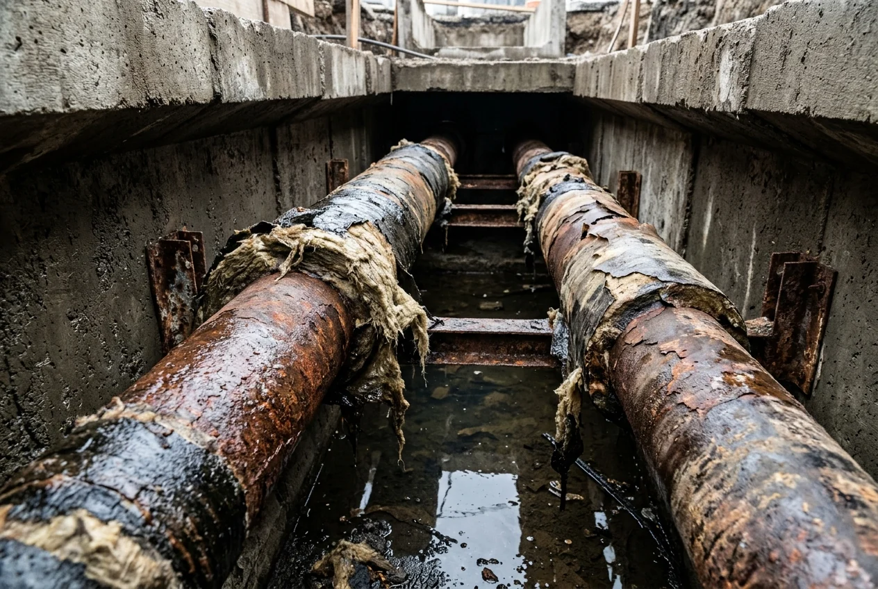
Once the hydrophobic binder dissolves, thermal losses escalate by an order of magnitude across the flooded concrete channel. Prior mineral-wool studies found that the effective thermal conductivity of wet mineral wool is 50-fold larger than the dry sample, and Aspen Aerogel tests reveal that submerged wet insulation experiences over 30-fold greater heat loss compared to dry insulation. During hot-water submersion of mineral wool pipe insulation, the measured heat loss rate reaches a plateau of 2290 W (with a 3-D simulation prediction of 2254 W) and a time-averaged measured heat loss of 1909 W. In the dry period, measured and predicted heat flow through the mineral wool pipe section averaged Qi = 60 W, whereas submerging the mineral wool in water caused a heat loss of about 2 kW per meter.
Corrosion under insulation (CUI) risk increases at pipe temperatures of -4°C to 175°C (25°F to 350°F), and open-cell insulations like mineral wool retain infiltrating water within the insulation body rather than draining freely. In 720-hour modified ASTM G189 cyclic wet/dry testing (60°C / 140°F wet and 150°C / 302°F dry), steel pipe insulated with uninhibited mineral wool suffered an average uniform corrosion rate of 358.18 µm/year (14.10 MPY), compared to 8.53 µm/year (0.34 MPY) for mineral wool with corrosion inhibitors. Preserving downstream building heat supply therefore requires coordinating pipeline replacement with building-side upgrades in panel building energy retrofits and heating substations.
Ultrasonic Wall-Thickness Inspection and Service Pipe Dimension Benchmarks
Deciding whether an excavated steel heating line can accept a localized weld repair or requires full segment replacement depends on ultrasonic wall-thickness mapping against normative steel pipe wall minimums. Where non-walkable concrete channels or road crossings prevent direct external access, internal ultrasonic crawlers quantify remaining wall thickness along the carrier pipe:
- In the CPCU Paris concrete-channel district heating network (operating at 235 °C / 455 °F and 20 bar / 290 psi), an ultrasonic pipe robot scanned 100 per cent of the interior surface of a 260 mm inner-diameter, 6.5 mm wall-thickness steel condensate-return line along 60 metres through five bends to quantify wall-thickness reduction from corrosion.
- In Bremerhaven’s 15-kilometre buried district heating network (120 °C / 248 °F, 5 to 6 bar / 72 to 87 psi), an ultrasonic pulse-echo robot using water coupling was deployed after pipe temperatures cooled below 45 °C (113 °F) to measure external corrosion wall-thickness reductions along 100 metres of a 235 mm inner-diameter, 5.2 mm wall-thickness spirally welded steel line.
When ultrasonic inspection reveals external wall thinning or when procurement engineers specify new district heating pipes, manufacturing and dimensional acceptance follow strict steel certification and wall-thickness tables. All steel pipes and components used for manufacturing bonded pipe assemblies shall as a minimum be delivered to the manufacturer with an inspection certificate 3.1 according to EN 10204. A straight factory length of steel service pipe shall not include a circular weld. Steel service pipe wall thicknesses t and masses shall comply with EN 10220 with a minimum as indicated in Table 1, and wall thickness tolerances shall comply with EN 10216-2, EN 10217-2, or EN 10217-5.
- In EN 253:2019 Table 1, minimum steel service pipe outside diameter (do) and wall thickness (t) are: DN 15 (21,3 mm, 2,0 mm), DN 20 (26,9 mm, 2,0 mm), DN 25 (33,7 mm, 2,3 mm), DN 32 (42,4 mm, 2,6 mm), DN 40 (48,3 mm, 2,6 mm), DN 50 (60,3 mm, 2,9 mm), DN 65 (76,1 mm, 2,9 mm), and DN 80 (88,9 mm, 3,2 mm).
- In EN 253:2019 Table 1, steel service pipe outside diameter (do) and minimum wall thickness (t) are: DN 100 (114,3 mm, 3,6 mm), DN 125 (139,7 mm, 3,6 mm), DN 150 (168,3 mm, 4,0 mm), DN 200 (219,1 mm, 4,5 mm), DN 250 (273,0 mm, 5,0 mm), and DN 300 (323,9 mm, 5,6 mm).
- In Table 1, large-bore steel service pipe outside diameter and minimum wall thickness are: DN 350 (355,6 mm, 5,6 mm), DN 400 (406,4 mm, 6,3 mm), DN 500 (508,0 mm, 6,3 mm), DN 600 (610,0 mm, 7,1 mm), DN 700 (711,0 mm, 8,0 mm), DN 800 (813,0 mm, 8,8 mm), DN 900 (914,0 mm, 10,0 mm), DN 1 000 (1 016,0 mm, 11,0 mm), and DN 1 200 (1 219,0 mm, 12,5 mm).
- Comparing AGFW 401 wall thickness (t1) against EN 253 wall thickness (t2), small-bore steel pipes have thicker walls under AGFW 401: DN 20 (2,6 vs 2,0), DN 25 (2,6 vs 2,3), DN 32 and DN 40 (3,2 vs 2,6), and DN 50 and DN 65 (3,2 vs 2,9), converging at DN 80 (3,2).
| Nominal diameter group | Standard or engineering benchmark | Outside diameter (do) and minimum wall thickness (t) |
|---|---|---|
| Small-bore distribution pipes (DN 15 to DN 80) | EN 253:2019 Table 1 | DN 15 (21,3 mm, 2,0 mm), DN 20 (26,9 mm, 2,0 mm), DN 25 (33,7 mm, 2,3 mm), DN 32 (42,4 mm, 2,6 mm), DN 40 (48,3 mm, 2,6 mm), DN 50 (60,3 mm, 2,9 mm), DN 65 (76,1 mm, 2,9 mm), and DN 80 (88,9 mm, 3,2 mm) |
| Small-bore thickened wall option (DN 20 to DN 80) | AGFW 401 (t1) vs EN 253 (t2) | DN 20 (2,6 vs 2,0), DN 25 (2,6 vs 2,3), DN 32 and DN 40 (3,2 vs 2,6), and DN 50 and DN 65 (3,2 vs 2,9), converging at DN 80 (3,2) |
| Medium-bore feeder mains (DN 100 to DN 300) | EN 253:2019 Table 1 | DN 100 (114,3 mm, 3,6 mm), DN 125 (139,7 mm, 3,6 mm), DN 150 (168,3 mm, 4,0 mm), DN 200 (219,1 mm, 4,5 mm), DN 250 (273,0 mm, 5,0 mm), and DN 300 (323,9 mm, 5,6 mm) |
| Large-bore transmission mains (DN 350 to DN 1 200) | EN 253:2019 Table 1 | DN 350 (355,6 mm, 5,6 mm), DN 400 (406,4 mm, 6,3 mm), DN 500 (508,0 mm, 6,3 mm), DN 600 (610,0 mm, 7,1 mm), DN 700 (711,0 mm, 8,0 mm), DN 800 (813,0 mm, 8,8 mm), DN 900 (914,0 mm, 10,0 mm), DN 1 000 (1 016,0 mm, 11,0 mm), and DN 1 200 (1 219,0 mm, 12,5 mm) |
EN 253 Bonded Composite Structure: Steel Service Pipe, PUR Foam, and PE 80 Casing
Directly buried pre-insulated district heating pipes eliminate concrete channels by locking the steel carrier pipe, rigid polyurethane foam, and high-density polyethylene casing into a single shear-transferring composite. Achieving composite action begins with steel surface preparation before foaming. Prior to thermal insulation, the outer surface of the steel service pipe shall be cleaned free of rust, mill scale, oil, grease, dust, paint, and moisture, and before cleaning it shall comply with rust grade A, B, or C according to EN ISO 8501-1, without pitting. According to the EN253 standard published in 2019, the minimum lifetime of a district heating pipe used continuously at temperatures up to 120°C must be 30 years, while at operating temperatures below 115°C the pipes may last for more than 50 years.
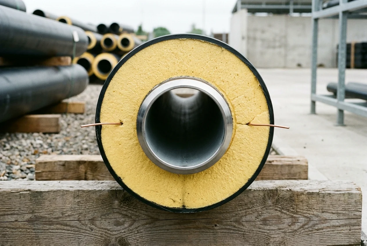
Within the composite annulus, rigid polyurethane (PUR) foam provides both low thermal conductivity and mechanical shear transfer between the heated steel carrier pipe and the soil-restrained outer casing:
- PUR foam thermal insulation shall have an average radial cell size of less than 0,5 mm, a closed cell content of not less than 88 %, and an average area of voids and bubbles not exceeding 5 % of the PUR cross-sectional area.
- The PUR foam compressive strength or compressive stress at 10 % relative deformation (as defined in EN ISO 844) shall be not less than 0,3 MPa in a radial direction.
- According to EN253, the maximum initial thermal conductivity of rigid PUR foam should not exceed 0.029 W/(m K) at 50°C. Cyclopentane blowing gas has a thermal conductivity of 0.013 W/mK at 25°C; PUR foams consist of 92–98% closed cells.
- Minimum axial shear strength requirements between the steel service pipe and PUR foam are 0.12 MPa at 23 ± 2 °C and 0.08 MPa at 140 ± 2 °C (both unaged and aged).
- Citing EN 253, PUR insulation requirements include thermal conductivity below 0,029 W/m·K (with Set Pipes achieving 0,026 W/m·K), continuous heat resistance above 130°C/30 years (chapter 4.5.5.1), and water absorption below 10% of sample mass (chapter 4.4.5); separately, the Set Pipes handbook lists its own radial shear strength figure of above 0,20 MPa at 140°C.
Protecting the polyurethane core against groundwater and soil friction requires a stress-crack-resistant polyethylene outer jacket. The black extruded polyethylene casing material shall be tested in accordance with EN ISO 9080 and classified as at least a PE 80 material in accordance with EN ISO 12162. The thermal stability (oxygen induction time, OIT) of the black PE casing material shall be at least 20 min when tested at 210 °C according to EN ISO 11357-6. In Table 2, PE casing minimum wall thickness (emin) increases from 3,0 mm (Dc 90 mm to 180 mm) and 3,6 mm (Dc 250 mm) to 4,8 mm (Dc 400 mm), 5,6 mm (Dc 500 mm), 6,6 mm (Dc 630 mm), 7,9 mm (Dc 800 mm), 9,4 mm (Dc 1 000 mm), 11,0 mm (Dc 1 200 mm), and 12,5 mm (Dc 1 400 mm). PE casing ends shall be square within 2,5°, elongation at break shall not be less than 350 %, longitudinal heat reversion under EN ISO 2505 shall not change by more than 3 %, and stress crack resistance time to failure shall not be less than 300 h.
Thermal Expansion Pre-Heating, Watertight Field Joints, and Surveillance Loops
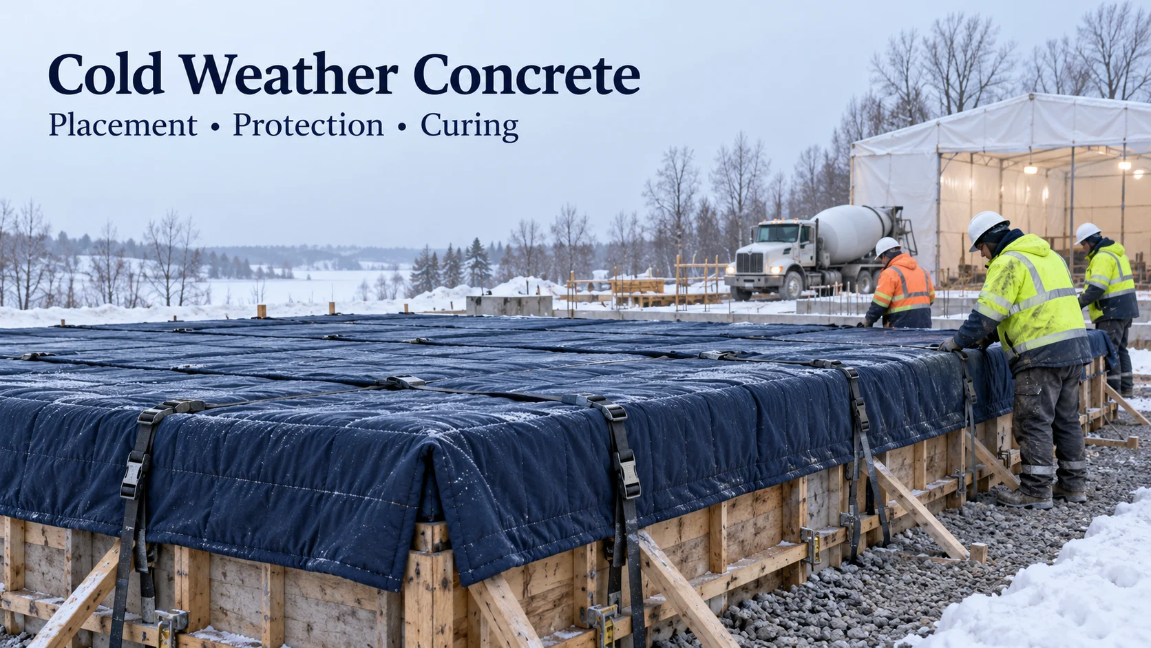
Long-term reliability of a directly buried district heating system depends on controlling axial thermal stresses during installation, sealing every field joint against groundwater, and commissioning embedded copper surveillance loops before trench reinstatement. EN13941-1 (2019) specifies design, calculation, and installation requirements for directly buried bonded hot water piping systems operating continuously with treated hot water at temperatures up to 120 deg. C, with occasional peak temperatures up to 140 deg. C and a maximum internal pressure of 2.5 MPa. When winter construction schedules require pouring concrete anchor blocks or chamber walls along the pipeline route, follow the thermal protection rules in cold-weather concrete reconstruction pours.
Worked Calculation: Open-Trench Thermal Pre-Heating Stress Reduction
Because soil friction restrains the buried composite pipe once backfilled, heating the pipeline up to an average temperature between soil temperature and maximum forward-flow temperature prior to final trench restraint halves the resulting axial stress amplitude. Pre-heating a buried bonded steel pipeline to the average temperature halves the tensile and compressive stress compared to cold laying; using ESt = 210 GPa and expansion coefficient 12,6 x 10⁻⁶ K-1, a 2.100m DN 250 pipeline at 125°C max and 10°C soil temperature (57,5 K change) expands 1,5 m at each end with a steel stress of ±152 N/mm2.
Watertight Field Joint Assemblies and Dual-Sealing Closures
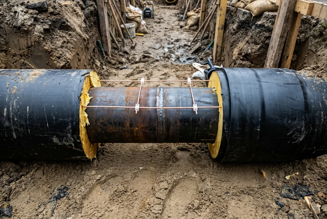
Every field weld between straight pipe lengths requires a casing closure that matches the mechanical and thermal insulation performance of the factory pipe:
- EN 489-1:2019 Clauses 1 and 4.2.2 require joints between adjacent factory-made pipe, fitting, and valve assemblies in buried hot water networks (per EN 13941-1) to be watertight and able to withstand radial forces and bending moments.
- Under Clauses 4.3.2 and 4.3.3, welds between steel service pipes shall conform to EN 13941-2, and joint PUR insulation shall completely fill the joint and meet EN 253 requirements for foam density, compressive strength, radial cell size, and water absorption at elevated temperature.
- Under Clauses 4.3.6 and 4.3.8, each circumferential and longitudinal joint casing weld tested for stress crack resistance (SCR) shall have a time to failure of at least 300 h, and welded plugs shall have a melt mass-flow rate (MFR) within 0,2 ≤ MFR ≤ 1,0 g/10 min.
- Under UK Heat Network Technical Standard TS1 (Clauses 2.16.6, 2.16.7, and 2.16.12), buried joint closures shall allow an air test against groundwater ingress, shrink-sleeve joints shall include an additional protection seal at each end (‘dual sealing’), and thermal expansion of buried pipework shall use expansion bends/loops while avoiding expansion bellows.
Embedded Copper Surveillance Wires and Fault Location Acceptance
Integrating continuous electrical leak detection into new district heating pipes allows utility operators to detect and locate moisture ingress at a joint or casing defect before external corrosion perforates the steel carrier pipe. EN 14419:2019 Clause 1 specifies requirements and test methods for electrical-wire-based surveillance systems forming an integral part of pipes, valves, fittings, and joints in directly buried hot water networks in accordance with EN 13941-1 and EN 13941-2. Measuring wires within pipe elements shall have no electrical contact with each other, the service pipe, or any conductive diffusion barrier, and wire connections are prohibited inside straight pipe elements (accepted only inside T-fittings). The distance between the measuring wire and the steel service pipe should be a minimum of 10 mm (Clause 6.3.4), and measuring wires led out at the end of the thermal insulation shall exceed the length of the service pipe by a minimum of 20 mm (Clause 6.5.1). Under Clause 7.4, ordinary electrical wire or any other kind of unauthorised wire is not allowed to form part of the field joint surveillance assembly.
In Nordic resistance and impedance surveillance installations, commissioning engineers verify loop continuity, insulation resistance, pulse-echo impedance, and galvanic potential before signing off on contractor civil works packages prepared under construction cost estimation for donor-funded projects:
- In the Nordic surveillance system (LOGSTOR Detect), each pre-insulated pipe contains 2 embedded copper alarm wires of 1.5 mm2 cross-section (one tinned) placed at equal distance from the service pipe; if heating medium conductivity exceeds 10µS/m, both resistance and impedance detectors can be used.
- For a 1.5 mm2 copper surveillance alarm wire, the nominal loop wire resistance is approximately 1.2 Ω per 100 m of wire.
- A faultless 1000 m copper surveillance wire has a loop resistance of 12 Ω (0.012 Ω per 1 m wire), whereas the surveillance detector defines a wire resistance of 200 Ω (> 200 Ω) as a broken wire.
- The commissioning acceptance criterion for PUR insulation resistance between the copper alarm wire and steel service pipe is ≥ 10 MΩ per km of wire, and pipe systems with less than 1 km of wire require a minimum insulation resistance of 10 MΩ.
- Time Domain Reflectometry (TDR) impedance measurement locates faults along pre-insulated pipes across a characteristic impedance Z of ~200 Ω, with subsequent deviation acceptance criteria typically limited to a maximum of 50-100 ‰ relative to the commissioning master curve.
- When moisture or water acts as an electrolyte between the copper alarm wire and steel service pipe in moist PUR insulation, a galvanic voltage typically between 0.2-0.7V is registered, with commissioning alarm limits typically set at > 0.2-0.4V.
| Verification stage | Governing standard or system benchmark | Mandatory acceptance threshold or engineering rule |
|---|---|---|
| Steel pipe mill certification and weld restriction | EN 253:2019 Clauses 4.2.1 and 4.2.3 | All steel pipes and components used for manufacturing bonded pipe assemblies shall as a minimum be delivered to the manufacturer with an inspection certificate 3.1 according to EN 10204; a straight factory length of steel service pipe shall not include a circular weld |
| PUR foam cell structure and compressive strength | EN 253:2019 Clauses 4.4.2 and 4.4.3 | PUR foam thermal insulation shall have an average radial cell size of less than 0,5 mm, a closed cell content of not less than 88 %, and an average area of voids and bubbles not exceeding 5 % of the PUR cross-sectional area; compressive strength at 10 % relative deformation (EN ISO 844) shall be not less than 0,3 MPa |
| PE casing classification and thermal stability | EN 253:2019 Clauses 4.3.1.1 and 4.3.1.3 | Black extruded polyethylene casing material shall be tested in accordance with EN ISO 9080 and classified as at least a PE 80 material in accordance with EN ISO 12162; thermal stability (OIT) shall be at least 20 min when tested at 210 °C according to EN ISO 11357-6 |
| Field joint welding, foaming, and casing welds | EN 489-1:2019 Clauses 4.3.2, 4.3.3, 4.3.6, and 4.3.8 | Welds between steel service pipes shall conform to EN 13941-2, joint PUR insulation shall completely fill the joint and meet EN 253 requirements, each joint casing weld tested for stress crack resistance (SCR) shall have a time to failure of at least 300 h, and welded plugs shall have a melt mass-flow rate within 0,2 ≤ MFR ≤ 1,0 g/10 min |
| Surveillance wire geometry and loop commissioning | EN 14419:2019 Clauses 6.3.4, 6.5.1, 7.4 and Nordic surveillance handover | Distance between measuring wire and steel service pipe should be a minimum of 10 mm, wire free-end extension at least 20 mm, nominal loop resistance approximately 1.2 Ω per 100 m of 1.5 mm2 copper wire (12 Ω per 1000 m; > 200 Ω broken wire), and PUR insulation resistance ≥ 10 MΩ per km of wire (minimum 10 MΩ for < 1 km) |
Sources
- European Committee for Standardization, District heating pipes — Preinsulated bonded pipe systems for directly buried hot water networks — Factory made pipe assembly of steel service pipe, polyurethane thermal insulation and a casing of polyethylene
- European Committee for Standardization, District heating pipes — Preinsulated bonded pipe systems for directly buried hot water networks — Surveillance systems for directly buried hot water networks
- European Committee for Standardization, District heating pipes — Preinsulated bonded pipe systems for directly buried hot water networks — Joint casing assemblies for steel service pipes, polyurethane thermal insulation and a casing of polyethylene
- Chalmers University of Technology Department of Chemistry and Chemical Engineering, Degradation of Polyurethane Foam in District Heating Pipes
- International Journal of Heat and Mass Transfer, Thermal Conductivity and Heat Loss of Wet Mineral Wool Pipe Insulation
- National Insulation Association, Corrosion Under Insulation Testing of Mineral Wool Pipe Insulation
- World Bank Energy and Extractives Global Practice, Ukraine District Heating Energy Efficiency Project Appraisal Document
- United Kingdom Department for Energy Security and Net Zero, Heat Network Technical Assurance Scheme Technical Specifications
- Inspector Systems Automated Ultrasonic Pipe Inspection, Ultrasonic Test Robots in District Heating Pipelines
- Set Pipes Technical Engineering Handbook and Logstor Detect Surveillance System Handbook
- International Institute of Refrigeration and Euroheat and Power, European District Heating and Cooling Market Outlook
- Ministry of Energy of Ukraine and European Commission, Ukraine Energy Support Fund Municipal Heat Supply Assistance